Servo Control with MPU6050 and NodeMcu
In this tutorial, we will explore how to control a servo motor using the MPU6050 gyroscope and accelerometer sensor with a NodeMCU ESP8266. This project is perfect for beginners who want to dive into sensor-based control systems, especially in robotics. By the end, you’ll learn how to map the tilt of the MPU6050 sensor to control a servo motor.
Materials Required
To follow along, ensure you have the following components:
NodeMCU ESP8266
MPU6050 Gyroscope and Accelerometer Sensor
Servo Motor
Breadboard
Jumper Wires
External 5V Power Supply (for the servo motor)
How It Works
The MPU6050 sensor detects motion and orientation by measuring acceleration and angular velocity. We will use its gyroscope data (specifically the X-axis) to control the angle of the servo motor. The NodeMCU will read the sensor data via I2C communication and adjust the servo’s position accordingly.
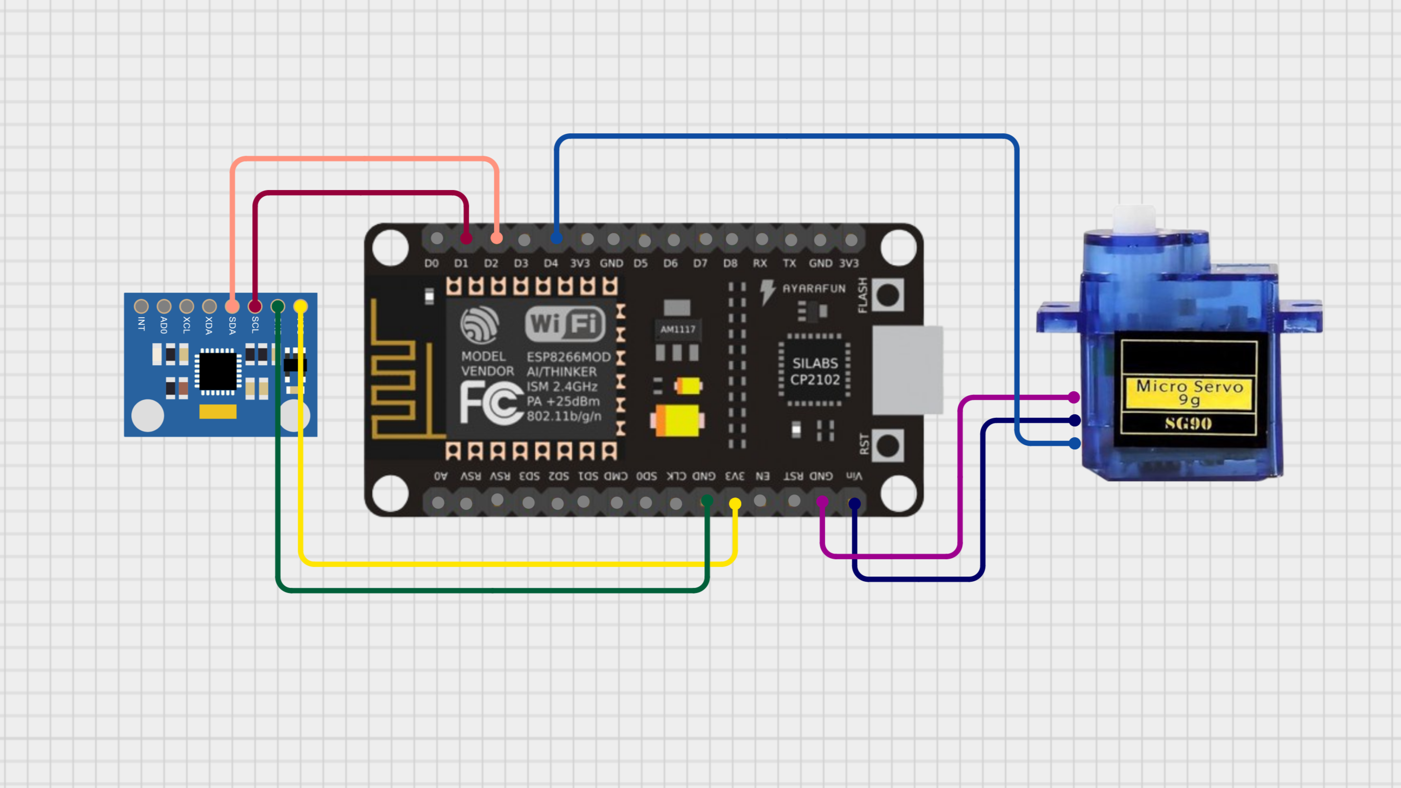
Circuit Diagram

Connections
MPU6050 to NodeMCU:
VCC → 3.3V
GND → GND
SCL → D1 (GPIO 5)
SDA → D2 (GPIO 4)
Servo Motor to NodeMCU:
VCC → External 5V Power Supply
GND → Common GND
Signal → D4 (GPIO 2)
Note: Since the servo motor requires 5V, it’s important to power it externally while ensuring all grounds are connected.
Arduino Code
Here is the complete code to control the servo motor:
#include <Adafruit_MPU6050.h>
#include <Adafruit_Sensor.h>
#include <Wire.h>
#include <Servo.h>

Adafruit_MPU6050 mpu;
Servo myServo;

const int servoPin = D4; // Define the pin for the servo signal
int servoAngle = 90;    // Initialize the servo at 90 degrees (neutral position)

float gyroX_offset = 0; // Offset for gyro X-axis

void setup() {
  Serial.begin(115200);
  mpu.begin();

  // Set ranges for sensor sensitivity
  mpu.setAccelerometerRange(MPU6050_RANGE_8_G);
  mpu.setGyroRange(MPU6050_RANGE_500_DEG);
  mpu.setFilterBandwidth(MPU6050_BAND_21_HZ);

  // Attach the servo
  myServo.attach(servoPin);
  myServo.write(servoAngle);

  // Calibrate gyroscope
  gyroX_offset = calibrateGyro();
  Serial.print("Calibration complete. Gyro X offset: ");
  Serial.println(gyroX_offset);
}

void loop() {
  sensors_event_t a, g, temp;
  mpu.getEvent(&a, &g, &temp);

  // Adjust gyro X reading
  float gyroX = g.gyro.x - gyroX_offset;

  // Update servo angle based on gyro reading
  servoAngle += gyroX * 10; // Adjust sensitivity with multiplier
  servoAngle = constrain(servoAngle, 0, 180);

  // Move servo
  myServo.write(servoAngle);

  // Debugging information
  Serial.print("Gyro X: ");
  Serial.print(gyroX);
  Serial.print(" rad/s | Servo Angle: ");
  Serial.println(servoAngle);

  delay(50); // Small delay for stability
}

float calibrateGyro() {
  const int calibrationTime = 5000; // Calibration time in milliseconds
  int sampleCount = 0;
  float gyroX_sum = 0;

  unsigned long startTime = millis();
  while (millis() - startTime < calibrationTime) {
    sensors_event_t a, g, temp;
    mpu.getEvent(&a, &g, &temp);

    gyroX_sum += g.gyro.x;
    sampleCount++;
    delay(10);
  }

  return gyroX_sum / sampleCount;
}
Code Explanation
1. Importing Libraries
#include <Adafruit_MPU6050.h>
#include <Adafruit_Sensor.h>
#include <Wire.h>
#include <Servo.h>
These libraries handle communication with the MPU6050 sensor and control of the servo motor.
2. Object Initialization
Adafruit_MPU6050 mpu;
Servo myServo;
mpu: Initializes the MPU6050 object to read sensor data.
myServo: Creates an object to control the servo motor.
3. Variables and Constants
const int servoPin = D4;
int servoAngle = 90;
float gyroX_offset = 0;
servoPin: GPIO pin for controlling the servo motor.
servoAngle: Stores the current position of the servo (initially 90°).
gyroX_offset: Used for calibrating the gyroscope to remove drift.
4. Setup Function
void setup() {
  Serial.begin(115200);
  mpu.begin();
  mpu.setAccelerometerRange(MPU6050_RANGE_8_G);
  mpu.setGyroRange(MPU6050_RANGE_500_DEG);
  mpu.setFilterBandwidth(MPU6050_BAND_21_HZ);
  myServo.attach(servoPin);
  myServo.write(servoAngle);
  gyroX_offset = calibrateGyro();
}
Initializes the sensor and servo motor.
Configures sensitivity ranges for the accelerometer and gyroscope.
Calibrates the gyroscope to calculate the gyroX_offset.
5. Main Loop
void loop() {
  sensors_event_t a, g, temp;
  mpu.getEvent(&a, &g, &temp);
  float gyroX = g.gyro.x - gyroX_offset;
  servoAngle += gyroX * 10;
  servoAngle = constrain(servoAngle, 0, 180);
  myServo.write(servoAngle);
  Serial.print("Gyro X: ");
  Serial.print(gyroX);
  Serial.print(" rad/s | Servo Angle: ");
  Serial.println(servoAngle);
  delay(50);
}
Reads data from the MPU6050.
Adjusts the servo angle based on the gyroscope X-axis reading.
Ensures the servo angle stays within valid bounds (0° to 180°).
Moves the servo motor to the new position.
6. Calibration Function
float calibrateGyro() {
  const int calibrationTime = 5000;
  int sampleCount = 0;
  float gyroX_sum = 0;
  unsigned long startTime = millis();
  while (millis() - startTime < calibrationTime) {
    sensors_event_t a, g, temp;
    mpu.getEvent(&a, &g, &temp);
    gyroX_sum += g.gyro.x;
    sampleCount++;
    delay(10);
  }
  return gyroX_sum / sampleCount;
}
Collects gyroscope readings over 5 seconds.
Computes the average X-axis reading to remove drift.
Testing the Project
Connect the NodeMCU to your computer and upload the code using the Arduino IDE.
Open the Serial Monitor at a baud rate of 115200 to view the gyroscope readings and servo angle.
Tilt the MPU6050 sensor along the X-axis and observe the servo motor moving accordingly.
Troubleshooting Tips
Check your wiring: Ensure all connections are secure and correct.
External Power: Use a reliable 5V power supply for the servo motor.
Library Installation: Verify that the Adafruit libraries are installed in the Arduino IDE.
Gyroscope Calibration: Restart the system if the servo behaves erratically.


